Introduction to Electronics
Senior 6 · Physics
Introduction to Electronics
Lesson 5 of 5
25 min
On 12 September 1958, Jack Kilby of Texas Instruments showed his managers a sliver of germanium about a centimetre long, with a transistor, resistors and a capacitor all made in the same piece of semiconductor and joined by fine gold wires. When he connected it, a steady sine wave appeared on the oscilloscope: the first integrated circuit. A few months later Robert Noyce, at Fairchild Semiconductor, showed how to make such circuits flat on a silicon chip, with the connections printed on top. Kilby received the Nobel Prize in Physics in 2000. In 1971 the first single-chip microprocessor, the Intel 4004, held about 2300 transistors; a modern phone processor holds billions, each one a switch of the kind you met in Lesson 4. This lesson shows how such switches are combined into logic gates, the building blocks of every digital device.

An integrated circuit (IC) is made by repeatedly coating a silicon wafer, exposing it to light through a patterned mask (photolithography), etching, and diffusing in dopants, so that hundreds of identical chips, each containing transistors, diodes, resistors, capacitors and their connections, are made at once. Each chip is then sealed in a package with metal pins, such as the dual in-line package (DIL), with two rows of pins.
| Advantage of an IC over separate components | Why |
|---|---|
| very small and light | components are micrometres or nanometres across |
| cheap per function | thousands of chips are made together on one wafer |
| reliable | few soldered joints to fail |
| fast and low-power | tiny distances and tiny currents |
ICs are of two broad kinds. Analogue ICs handle continuously varying signals: amplifiers, voltage regulators, radio receivers. Digital ICs handle signals that are only ever in one of two states: logic gates, memories and microprocessors. The limits are heat (a small chip cannot shed much power) and the high cost of designing a new chip, which pays off only when millions are made.
Definition
An integrated circuit (IC) is a complete electronic circuit, with its transistors, other components and connections, made on a single small piece (chip) of semiconductor. Example: the 7400 chip contains four independent NAND gates.
A logic gate is a digital circuit whose output is either 0 or 1, decided by a fixed rule (a Boolean function) from its inputs, which are also 0 or 1. Example: an AND gate gives 1 only when all its inputs are 1.
In a digital circuit, every p.d. is read as one of two logic levels: 1 (HIGH, near the supply p.d., for example 5 V) or 0 (LOW, near 0 V). A range of p.d.s counts as each level, with a forbidden band between, so small amounts of noise do not change the value. This is why digital signals can be copied and sent over long distances without errors building up. Each variable (A, B, …) is a Boolean variable, and a gate's behaviour is fully described by its truth table, which lists the output for every combination of inputs: rows for inputs.
Figure 5.1: Logic-gate symbols (IEC 60617). Many books, and many data sheets, use the older American "distinctive-shape" symbols instead; the logic is the same.
| A | B | AND A·B | OR A + B | NAND | NOR | XOR A ⊕ B |
|---|---|---|---|---|---|---|
| 0 | 0 | 0 | 0 | 1 | 1 | 0 |
| 0 | 1 | 0 | 1 | 1 | 0 | 1 |
| 1 | 0 | 0 | 1 | 1 | 0 | 1 |
| 1 | 1 | 1 | 1 | 0 | 0 | 0 |
The NOT gate (inverter) has one input: , so 0 gives 1 and 1 gives 0. In Boolean algebra the dot means AND, the plus means OR (so ), and a bar means NOT. NAND and NOR are AND and OR followed by NOT: and . XOR (exclusive OR) gives 1 when the inputs are different.
Figure 5.2: A transistor NOT gate.
This is the switching circuit of Lesson 4 read in logic terms. When A = 0, there is no base current, the transistor is cut off, no current flows in the 1 kΩ resistor and the output is at 5 V: Q = 1. When A = 1, the base current saturates the transistor and the output falls to about 0.2 V: Q = 0. Putting two transistors in series in place of one gives a NAND gate (the output falls only if both are on); putting them in parallel gives a NOR gate. Real logic ICs use more refined circuits, but the principle is the same.
Worked example 1: a transistor gate
In Figure 5.2 the transistor has . (a) When A = 5 V, find the base current, the largest collector current the 1 kΩ resistor allows, and show that the transistor saturates. (b) What is the output when A = 0?
Solution
(a) . The collector current cannot exceed . Since , the transistor saturates and Q ≈ 0.2 V = logic 0.
(b) No base current, so no collector current and no p.d. across the 1 kΩ resistor: Q = 5 V = logic 1 (as long as the next stage draws little current).
Gates can be joined to carry out any rule that can be written as a truth table. A designer writes the rule in words, turns it into a Boolean expression, draws the circuit and checks it with a truth table.
For example, a water pump P that fills a school's storage tank from a well should run when the tank is not full (F = 0) and there is water in the well (W = 1), or whenever the manual override M is pressed. So .
Figure 5.3: Logic for the pump controller.
Worked example 2: the truth table of the pump controller
Complete the truth table for , and state in how many of the 8 input combinations the pump runs.
Solution
| M | F | W | F̄ | F̄·W | P |
|---|---|---|---|---|---|
| 0 | 0 | 0 | 1 | 0 | 0 |
| 0 | 0 | 1 | 1 | 1 | 1 |
| 0 | 1 | 0 | 0 | 0 | 0 |
| 0 | 1 | 1 | 0 | 0 | 0 |
| 1 | 0 | 0 | 1 | 0 | 1 |
| 1 | 0 | 1 | 1 | 1 | 1 |
| 1 | 1 | 0 | 0 | 0 | 1 |
| 1 | 1 | 1 | 0 | 0 | 1 |
The pump runs in 5 of the 8 combinations: all four with M = 1, and one more (M = 0, F = 0, W = 1). The intermediate columns make the working easy to check.
Computers add in binary. Adding two single bits gives a sum bit and a carry bit: , , , (one two and no units). The sum column is exactly XOR and the carry column is exactly AND, so two gates make a half adder (Figure 5.4). Chaining adders, with each stage passing its carry to the next, adds numbers of any length.
Figure 5.4: A half adder.
Worked example 3: everything from NAND
Show how to make (a) a NOT gate, (b) an AND gate and (c) an OR gate using only 2-input NAND gates, and count the gates needed.
Solution
(a) Join both inputs: . One gate.
(b) Follow a NAND with a NOT made as in (a): . Two gates.
(c) Invert each input first, then NAND them: . Checking with a truth table: it is 0 only when , i.e. A = B = 0, so it is A + B (this is De Morgan's theorem). Three gates.
Because NAND alone can build every other gate, it is called a universal gate; a manufacturer can make one gate design very well and use it everywhere.
Figure 5.5: Pins of the 7400 quad NAND chip.
Push a 7400 (or 74HC00) chip into a breadboard across the centre gap. Connect pin 14 to +5 V and pin 7 to 0 V. Connect two inputs (pins 1 and 2) to +5 V or 0 V with wire links (logic 1 or 0), and connect the output (pin 3) through a 470 Ω resistor to an LED and on to 0 V. Record the LED (on = 1) for all four input combinations and compare with the NAND truth table. Then use the other gates on the chip to build NOT, AND and OR as in Worked example 3. Care: never leave an input unconnected (it may float to either level), and do not exceed 5 V on the chip.


Warning
Common mistakes. (1) Reading A + B as arithmetic: in Boolean algebra (OR). (2) Confusing OR with XOR: OR gives 1 when at least one input is 1, XOR when exactly one is. (3) Missing rows of a truth table: inputs need rows; list them in binary order (000, 001, 010, …). (4) Forgetting the small circle in a symbol: it inverts the output.
Tip
Remember the IEC symbols by the label in the box: & means "all inputs 1" (AND); ≥1 means "at least one input 1" (OR); =1 means "exactly one input 1" (XOR). The circle on the output turns any of them into its opposite.
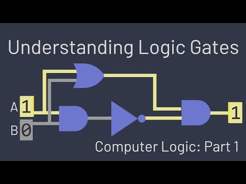
Understanding Logic Gates, by Spanning Tree. Watch how gates are built from transistor switches and combined to add binary numbers, then compare with the half adder in Figure 5.4.
Practice
Key points
Further reading
Sources and credits
Written by Ganzaa: the text, the five diagrams, the worked examples and the practice exercises. This lesson uses CC BY-SA images and is shared under CC BY-SA 4.0.