Introduction to Electronics
Senior 6 · Physics
Introduction to Electronics
Lesson 3 of 5
25 min
A socket in a Rwandan home supplies alternating current at 230 V, reversing direction 50 times every second (REG design voltage; the Rwanda Grid Code fixes the nominal frequency at 50 Hz). A phone battery needs a steady 5 V of direct current, always in one direction. Every charger, radio, laptop adaptor and solar inverter must therefore turn a.c. into d.c. Simple adaptors do it in three steps: a transformer lowers the voltage, a rectifier made of diodes makes the current flow one way only, and a smoothing capacitor fills in the gaps. Modern switch-mode chargers rectify the mains first and then use a high-frequency circuit to step it down, but the rectifier and the smoothing capacitor are still inside. In Unit 4 you found the mean value of a half-cycle of a.c.; here you use it.
Figure 3.1: A half-wave rectifier.
During each half-cycle in which the top of the secondary is positive, the diode is forward biased and current flows through the load. During the other half-cycle, the diode is reverse biased and no current flows. The output is a series of positive half-cycles separated by gaps (Figure 3.3(b)): it is unidirectional but far from steady.
Definition
Rectification is the conversion of alternating current into unidirectional (direct) current, using one or more diodes. A half-wave rectifier passes only one half of each cycle; a full-wave rectifier passes both halves, turning the negative half-cycles positive. Example: a single diode in series with a load is a half-wave rectifier.
Figure 3.2: A bridge rectifier.
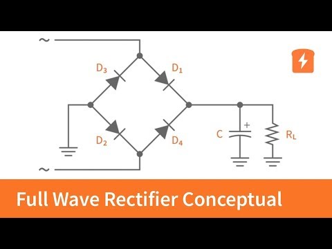
Four diodes arranged in a bridge use both halves of the cycle:
Either way, the current goes through the load in the same direction, so the output has two pulses per cycle (Figure 3.3(c)): peak , because two diodes conduct at a time; mean , twice the half-wave value; and a pulse frequency of 100 Hz. Each diode's PIV must exceed . An older design, the centre-tap full-wave rectifier, uses only two diodes with a transformer whose secondary has a connection at its midpoint; each diode then conducts on alternate half-cycles, but each must withstand a reverse p.d. of .
Figure 3.3: Waveforms for a 50 Hz supply. In (d) the dashed curve is the unsmoothed output.
Worked example 1: half-wave and full-wave compared
A transformer steps 230 V r.m.s. down to 12 V r.m.s. Find (a) the turns ratio, (b) the peak secondary p.d., and the peak and mean output p.d. of (c) a half-wave rectifier and (d) a bridge rectifier. Take 0.7 V per conducting diode for the peaks, and ignore the diode drops for the means.
Solution
(a) , a ratio of about 19 : 1.
(b) .
(c) Peak: ; mean: .
(d) Peak: ; mean: .
Comment: the bridge gives twice the mean output from the same transformer, at the cost of a second diode drop. With the drops included, the means are a little lower (about 5.2 V and 9.9 V).

A capacitor connected across the load (Figure 3.4) charges up to the peak p.d. while the diodes conduct. As the rectified p.d. falls after each peak, the diodes become reverse biased and the capacitor alone supplies the load, discharging through it: . Before it has discharged much, the next peak arrives and recharges it. The output becomes a nearly steady p.d. with a small sawtooth ripple (Figure 3.3(d)).
Figure 3.4: A reservoir (smoothing) capacitor. An electrolytic capacitor must be connected with its + terminal to the positive line.
Estimating the ripple. If the ripple is small, the load current is nearly constant, and the capacitor supplies it for almost the whole time between peaks, , where is the ripple frequency (50 Hz for half-wave, 100 Hz for full-wave on a 50 Hz supply). The charge lost is , so
Conditions: , so that the decay between peaks is nearly linear. A larger capacitor, a smaller load current or full-wave rectification all reduce the ripple. For a really steady output, a Zener regulator (Lesson 2) or a regulator IC follows the capacitor.
Worked example 2: choosing the reservoir capacitor
The bridge rectifier of Worked example 1 (peak 15.6 V, 50 Hz mains) supplies 100 mA. (a) What capacitance keeps the ripple to 1.0 V? (b) Check the condition . (c) What would the ripple be with the same capacitor and a half-wave rectifier?
Solution
(a) Full-wave, so : .
(b) The load resistance is about , so , sixteen times the 10 ms between peaks. The approximation is good.
(c) : , twice as much.
The output then varies between about 15.6 V and 14.6 V, a mean of about 15.1 V.

Use a low-voltage a.c. supply from the laboratory power pack (for example 6 V r.m.s.), never the mains directly. Connect a single diode and a 1 kΩ load (Figure 3.1) and display the p.d. across the load on an oscilloscope or a data logger, with the time base at 5 ms per division. Then build the bridge (or use a bridge package), and finally add 100 µF and then 1000 µF across the load, observing the polarity of the electrolytic capacitor. Record the peak p.d. and the ripple each time, and compare the ripple with .
Warning
Common mistakes and safety. (1) Using as the peak: the capacitor charges to minus the diode drops. (2) Using 50 Hz as the ripple frequency of a full-wave rectifier: it is 100 Hz. (3) Connecting an electrolytic capacitor the wrong way round: it can overheat and burst. (4) Mains voltages can kill: experiments use a low-voltage supply, and a charged reservoir capacitor can still give a shock after switch-off.
Tip
Three numbers describe any rectifier: the peak ( minus 0.7 V per conducting diode), the mean ( half-wave, full-wave) and the ripple once smoothed (). For the PIV, ask: "what is the biggest reverse p.d. this diode ever sees?"
Full Wave Rectifier: Conceptual Review, by CircuitBread. Follow the current through the diodes on each half-cycle and compare the output with Figure 3.3.
Practice
Key points
Sources and credits
Written by Ganzaa: the text, the four diagrams, the worked examples and the practice exercises.