Signals and Communication Systems
Senior 5 · Physics
Signals and Communication Systems
Lesson 1 of 4
25 min
When you speak into a phone in Kigali, your voice reaches a listener in Rusizi a fraction of a second later, after being changed into electrical signals, digits, radio waves and pulses of light in a glass fibre, and back again. Every step loses some of the signal's power and adds some unwanted noise. In Senior 3 you met analogue and digital signals and the main channels. This unit treats them quantitatively, as an engineer does: how much power is lost, how noise is measured, how a voice becomes a stream of bits, and how a radio wave carries it.
Every communication system, from a talking drum to a 5G network, has the same parts:
An analogue signal varies continuously and can take any value within its range, as the voltage from a microphone does. A digital signal takes only a limited set of values, usually two (0 and 1), and changes only at fixed time intervals. Digital signals are sent as bits, and the number of bits sent each second is the bit rate, in bits per second (bit s⁻¹).
Definition
Attenuation is the gradual loss of a signal's power as it travels through a channel. Noise is any unwanted random signal added to the wanted one, for example from the thermal motion of electrons in the receiver, lightning or nearby electrical machines. The bandwidth of a signal is the range of frequencies it occupies; the bandwidth of a channel is the range of frequencies it can carry. Example: telephone-quality speech uses roughly 300 Hz to 3400 Hz, a bandwidth of about 3.1 kHz.
Signal powers in a system can differ by factors of millions, so engineers compare them on a logarithmic scale. The ratio of two powers and , in decibels (dB), is
A gain of 10 dB is a factor of 10, 20 dB a factor of 100, 30 dB a factor of 1000, and 3 dB is almost exactly a factor of 2. A loss is a negative number of decibels. The great advantage is that gains and losses in a chain simply add: a cable that loses 15 dB followed by an amplifier that gains 20 dB gives an overall gain of 5 dB.
Cables and fibres are described by their attenuation per unit length, in dB km⁻¹. A good optical fibre loses only about 0.2 dB km⁻¹ at its best wavelength (1550 nm); a thin copper telephone pair loses several dB per kilometre, and much more at high frequencies.
The quality of a received signal is set by the signal-to-noise ratio (SNR), the ratio of signal power to noise power:
Amplifying a signal does not improve its SNR, because the noise already on it is amplified too, and the amplifier adds a little of its own.
Worked example 1: loss in a cable
A signal of power 10 mW enters a copper cable 5.0 km long whose attenuation is 3.0 dB km⁻¹. Find (a) the total loss in dB, (b) the output power and (c) the gain, in dB, of the amplifier needed to restore the signal to 10 mW.
Solution
(a) Loss dB.
(b) , so and mW.
(c) The amplifier must make up the 15 dB lost: a gain of 15 dB, a power factor of .
Worked example 2: signal-to-noise ratio
At the input of a receiver, the wanted signal has power 2.0 mW and the noise 5.0 μW. (a) Find the SNR in dB. (b) The receiver amplifies everything by 20 dB and adds no noise of its own. What is the SNR at its output?
Solution
(a) , so SNR dB.
(b) Signal and noise are both multiplied by 100, so their ratio is unchanged: the SNR is still 26 dB. A real amplifier adds noise, so the output SNR would be slightly lower.
Over a long link, the signal must be boosted many times. An analogue system uses amplifiers, which boost noise together with the signal, so noise accumulates from stage to stage and cannot be removed. A digital system uses regenerators: each one only has to decide, bit by bit, whether the received level is above or below a threshold, and then sends out a fresh, clean pulse. As long as the noise is not large enough to push a level across the threshold, the information arrives perfect, however many stages there are.
| Analogue transmission | Digital transmission | |
|---|---|---|
| Noise over many stages | Accumulates; cannot be removed | Removed at each regenerator |
| Errors | Gradual loss of quality | Few errors, and these can be detected and corrected with extra check bits |
| Processing | Hard to store, encrypt or compress | Easily stored, encrypted, compressed and mixed with other data |
| Bandwidth needed | Small (about 3 kHz for a phone call) | Larger (64 kbit s⁻¹ for an uncompressed phone call) |
| Equipment | Simple | Needs converters (ADC and DAC) |
Worked example 3: spacing the regenerators
A fibre link loses 0.20 dB km⁻¹. Its receivers work reliably provided the signal power arriving is at least 1.0% of the power sent. What is the greatest distance between regenerators?
Solution
A power ratio of 0.010 is dB, so the link may lose at most 20 dB.
Distance km.
A copper cable losing 3.0 dB km⁻¹ would need a regenerator every km, which is one reason long-distance links now use fibre.
Warning
Decibels are ratios, not amounts. "The signal is 20 dB" means nothing unless you say 20 dB relative to what. Also, decibels add, but the powers they represent multiply: two 10 dB losses make a 20 dB loss, a factor of 100, not 20.
Tip
Memorise four: 3 dB is ×2, 10 dB is ×10, 20 dB is ×100, 30 dB is ×1000. Most exam questions can be done by adding these.
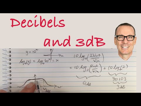
What are Decibels and why are 3dB and dBm important?, Iain Explains Signals, Systems, and Digital Comms. Watch how decibels turn multiplying gains into adding them, and why 3 dB means a factor of two.
Practice
Key points
Sources and credits
Written by Ganzaa. The two diagrams, the worked examples and the practice exercises are by Ganzaa.